Page 1 of 3 123 LastLast
Results 1 to 20 of 44
  1. #1
    cyberdan started this thread.
    cyberdan's Avatar
    SMF Badges of Honor


    Member since
    Feb 2013
    Location
    Del Norte County, CA
    Posts
    170
    Thanks
    8
    Thanked 111 Times in 47 Posts

    I am building electric wire stripper and need help.

    I want a certain type of wire stripper and can not find it anywhere for sale. I see one or two on youtube but the owners made them. I do not want any blades. I want two round wheels (like the rotor on an electric motor) one on top of each other. They can be touching but under pressure. Insert a solid core wire and the wire itself cuts off the insulation.

    Well now to get to my problem. I was scrapping a bread maker and saw this motor with a pully already assembled. I do not want the rotor to go very fast. I pulled everything out and today tested the motor to see how fast the rotor would turn. The motor looks brand new but does not run. Help.


    I hooked up wires C&D to an extension cord and all I got was a weak buzz from the motor. I also reversed the wires. I did nothing with A&B. I did open up the motor and all four wires are led directly into the stator windings. What do I need to add or how do I connect the wires to get it running?
    Name:  MOTOR-1.JPG
Views: 547
Size:  138.2 KB

    Here is the motor and pully assembly right from a bread maker.
    Name:  MOTOR-2.JPG
Views: 588
Size:  173.6 KB
    Here I am cyberdan, at yardsales I am dollardan


  2. #2
    SMF Badges of Honor


    Member since
    Jun 2017
    Location
    Las Vegas
    Posts
    1,306
    Thanks
    3,232
    Thanked 1,921 Times in 785 Posts
    Are you certain that a faulty motor is not why the breadmaker was scrapped?

  3. #3
    hills's Avatar
    SMF Badges of Honor


    Member since
    Sep 2017
    Location
    Maine
    Posts
    1,543
    Thanks
    827
    Thanked 1,364 Times in 796 Posts
    Dan,

    I didn't want to discourage you but i've been down this road before with building both the manual and machine strippers. There's quite a bit of time invested with working through all of the design details. First you build one model as a prototype and end up chasing improvements with every new build. It's called research & development.

    The heck of it is that there's no sense in re-inventing the wheel here. This R&D work has already been done by somebody else ages ago.

    You can just go and buy a fairly decent electric wire stripping machine for under 170 bucks on ebay. The machine will pay for itself in no time with copper prices being what they are these days.

    More to your question though: My guess would be that the two blue wires are your neutral/ground. The yellow and red wires would be hots. Maybe it would run at one speed with yellow energized and another speed with red. I would check the ohms on the individual coils with a multimeter to see if they are within spec. Look up the motor model electrical schematic and see if that gives any clue as to how to hook up the wires.

    Could be bad bearings, bad brushes, bad starting capacitor if it's buzzing like that. Also ... the extension cord could be bad. Could be that the gauge of the wire in the extension cord itself isn't heavy enough to handle the initial amp draw needed to get the motor running. ( seen that happen before.)

    Visually inspect the stator winding for any burnt spots. Also ... there may be a thermal overload wired in there somewhere. Those can go bad.

    Could try plugging it in and giving the motor shaft a twist with your fingers to get the motor spinning. (Just be sure to wear heavy rubber gloves as a safety precaution.) That might tell you something about why the motor isn't working.
    Last edited by hills; 10-11-2021 at 08:22 AM.

  4. The Following 2 Users say Thank You for This Post by hills:


  5. #4
    cyberdan started this thread.
    cyberdan's Avatar
    SMF Badges of Honor


    Member since
    Feb 2013
    Location
    Del Norte County, CA
    Posts
    170
    Thanks
    8
    Thanked 111 Times in 47 Posts
    Quote Originally Posted by JJinLV View Post
    Are you certain that a faulty motor is not why the breadmaker was scrapped?
    possible, I should have plugged it in before scrapping.

  6. #5
    cyberdan started this thread.
    cyberdan's Avatar
    SMF Badges of Honor


    Member since
    Feb 2013
    Location
    Del Norte County, CA
    Posts
    170
    Thanks
    8
    Thanked 111 Times in 47 Posts
    Quote Originally Posted by hills View Post
    I didn't want to discourage you but i've been down this road before with building both the manual and machine strippers. There's quite a bit of time invested with working through all of the design details.
    Yes, there is but it is fun and all the design details is in my head.

    Quote Originally Posted by hills View Post
    there's no sense in re-inventing the wheel here. This R&D work has already been done by somebody else ages ago.
    I know that but can you send me in the direction of the type I want? I have had a streipper where the wire sits in a groove and a blade slits the insulation.

    Quote Originally Posted by hills View Post
    You can just go and buy a fairly decent electric wire stripping machine for under 170 bucks on ebay.
    I saw one that had what I wanted plus several holes for groove and blade, it was several hundred dollars. and too big for my work area.

    Quote Originally Posted by hills View Post
    Could be bad bearings, bad brushes, bad starting capacitor if it's buzzing like that.
    no capacitor at all. do all motors need one? When I scrapped the machine I cut away everything that I thought had to do with bread making. I guess I tossed it, if it had one.

    Thanks for the other suggestions. I will check them out.

  7. #6
    SMF Badges of Honor


    Member since
    Apr 2015
    Posts
    2,168
    Thanks
    632
    Thanked 2,503 Times in 1,138 Posts
    Quote Originally Posted by cyberdan View Post
    I want a certain type of wire stripper and can not find it anywhere for sale. I see one or two on youtube but the owners made them. I do not want any blades. I want two round wheels (like the rotor on an electric motor) one on top of each other. They can be touching but under pressure. Insert a solid core wire and the wire itself cuts off the insulation.

    Well now to get to my problem. I was scrapping a bread maker and saw this motor with a pully already assembled. I do not want the rotor to go very fast. I pulled everything out and today tested the motor to see how fast the rotor would turn. The motor looks brand new but does not run. Help.

    I hooked up wires C&D to an extension cord and all I got was a weak buzz from the motor. I also reversed the wires. I did nothing with A&B. I did open up the motor and all four wires are led directly into the stator windings. What do I need to add or how do I connect the wires to get it running?
    Name:  MOTOR-1.JPG
Views: 547
Size:  138.2 KB

    Here is the motor and pully assembly right from a bread maker.
    Name:  MOTOR-2.JPG
Views: 588
Size:  173.6 KB

    Reconnect the start capacitor, your motor will run. But it's still the wrong motor for your project as it has a very low duty cycle

    Last edited by alloy2; 10-12-2021 at 01:06 AM.

  8. The Following User Says Thank You to alloy2 for This Post:


  9. #7
    cyberdan started this thread.
    cyberdan's Avatar
    SMF Badges of Honor


    Member since
    Feb 2013
    Location
    Del Norte County, CA
    Posts
    170
    Thanks
    8
    Thanked 111 Times in 47 Posts
    Quote Originally Posted by alloy2 View Post
    Reconnect the start capacitor, your motor will run. But it's still the wrong motor for your project as it has a very low duty cycle

    I remember seeing one of those black boxes. I probably tossed it, or it is in my ferris scrap boxes.

    I assume when you say low duty you mean after I use it for a while it will just turn off till it cools down?

    Thanks.

  10. #8
    SMF Badges of Honor


    Member since
    Apr 2015
    Posts
    2,168
    Thanks
    632
    Thanked 2,503 Times in 1,138 Posts
    Quote Originally Posted by cyberdan View Post
    I remember seeing one of those black boxes. I probably tossed it, or it is in my ferris scrap boxes.

    I assume when you say low duty you mean after I use it for a while it will just turn off till it cools down?

    Thanks.
    Duty cycle 30 minutes run time, the more expensive bread making machines may have a better motor.

    WHAT'S MOTOR DUTY CYCLE?

  11. #9
    SMF Badges of Honor


    Member since
    Apr 2015
    Posts
    2,168
    Thanks
    632
    Thanked 2,503 Times in 1,138 Posts
    If you wind a string around the pulley and give it a good pull to get the motor spinning then turn on the power it will run without the capacitor. Chances are rthe motor runs clockwise.

    When i was repairing fridges and freezers sometimes I would come across a stuck compressor, by connecting two caps to forward and revers the motor I could get it unstuck


  12. #10
    cyberdan started this thread.
    cyberdan's Avatar
    SMF Badges of Honor


    Member since
    Feb 2013
    Location
    Del Norte County, CA
    Posts
    170
    Thanks
    8
    Thanked 111 Times in 47 Posts
    Quote Originally Posted by alloy2 View Post
    If you wind a string around the pulley and give it a good pull to get the motor spinning then turn on the power it will run without the capacitor.
    Just like starting an old lawnmower. I might give it a try. thanks

  13. #11
    cyberdan started this thread.
    cyberdan's Avatar
    SMF Badges of Honor


    Member since
    Feb 2013
    Location
    Del Norte County, CA
    Posts
    170
    Thanks
    8
    Thanked 111 Times in 47 Posts
    Look what I found at the bottom of the bread maker shell. Pretty sure this is the capacitor that was attached. Even though it is marked 220V.

    So alloy2 how does everything connect up? Your pic helped but in my photo E & F go in but do not continue out.

    Would A & B be 110V in? and C & D just make a loop through the capacitor back into the motor?

    Name:  MOTOR-1.JPG
Views: 430
Size:  138.2 KB

    Name:  MOTOR-3.jpg
Views: 447
Size:  184.7 KB

  14. #12
    SMF Badges of Honor


    Member since
    Apr 2015
    Posts
    2,168
    Thanks
    632
    Thanked 2,503 Times in 1,138 Posts
    Quote Originally Posted by cyberdan View Post
    Look what I found at the bottom of the bread maker shell. Pretty sure this is the capacitor that was attached. Even though it is marked 220V.

    So alloy2 how does everything connect up? Your pic helped but in my photo E & F go in but do not continue out.

    Would A & B be 110V in? and C & D just make a loop through the capacitor back into the motor?

    Name:  MOTOR-1.JPG
Views: 430
Size:  138.2 KB

    Name:  MOTOR-3.jpg
Views: 447
Size:  184.7 KB
    Just rejoin the cut wires, the pair with the plug go to power switch and don't worry about the capacitor rating 220 volts this is the maximum voltage that maybe applied.

  15. #13
    cyberdan started this thread.
    cyberdan's Avatar
    SMF Badges of Honor


    Member since
    Feb 2013
    Location
    Del Norte County, CA
    Posts
    170
    Thanks
    8
    Thanked 111 Times in 47 Posts
    I decided to try the way I asked about in my above post. Works great. I know this is a light duty motor so if it burns out I will come to that problem when it does. The step down pully turns at just the speed I want.

    New question. I trimmed a cord off of a VCR to do the test. It is a three prong. I know the ground is the big prong. should I just attach the ground wire to the motor body or part of the frame?

  16. #14
    SMF Badges of Honor


    Member since
    Apr 2015
    Posts
    2,168
    Thanks
    632
    Thanked 2,503 Times in 1,138 Posts
    Quote Originally Posted by cyberdan View Post
    I decided to try the way I asked about in my above post. Works great. I know this is a light duty motor so if it burns out I will come to that problem when it does. The step down pully turns at just the speed I want.

    New question. I trimmed a cord off of a VCR to do the test. It is a three prong. I know the ground is the big prong. should I just attach the ground wire to the motor body or part of the frame?
    Yea you can secure the ground wire anywhere to the motor shell, have you connected the incoming AC power for the correct polarity.

    Motor will run either way, but the wrong polarization makes the motor shell and anything metal that its connected to live ( HOT) which could result in death.
    Last edited by alloy2; 10-16-2021 at 06:13 PM.

  17. #15
    SMF Badges of Honor


    Member since
    Apr 2015
    Posts
    2,168
    Thanks
    632
    Thanked 2,503 Times in 1,138 Posts
    There's a reason why one spade on a power plug is larger than the other.


  18. #16
    cyberdan started this thread.
    cyberdan's Avatar
    SMF Badges of Honor


    Member since
    Feb 2013
    Location
    Del Norte County, CA
    Posts
    170
    Thanks
    8
    Thanked 111 Times in 47 Posts
    Quote Originally Posted by alloy2 View Post
    have you connected the incoming AC power for the correct polarity.Motor will run either way, but the wrong polarization makes the motor shell and anything metal that its connected to live ( HOT) which could result in death.
    Very good question. I did all my testing with bare wire stuck in the white plastic plug. I did make sure not to touch any part of the motor assembly while it was plugged in. I checked and the motor did run either way when I plugged in the wires.

    I have no way to tell which wire is hot with the cord I used. I will toss it in my wire bin. I do have laptop cords that are like the pic shown. So the wide spade matches the square plug on the other end. Is this the hot wire?

    Gotta be extra careful today, very rainy today and my workshop is the back half of my greenhouse. (very dry on the workshop side)

  19. #17
    SMF Badges of Honor


    Member since
    Apr 2015
    Posts
    2,168
    Thanks
    632
    Thanked 2,503 Times in 1,138 Posts
    Wire color codes on offshore are confusing, for North America black is hot, white neutral with green to ground.

    Once you have the power connected with the motor running keep the ground wire disconnected then with your multi meter place one probe onto the motor shell with the other to the green ground.

    If polarization is incorrect your meter will show the motor shell is hot.

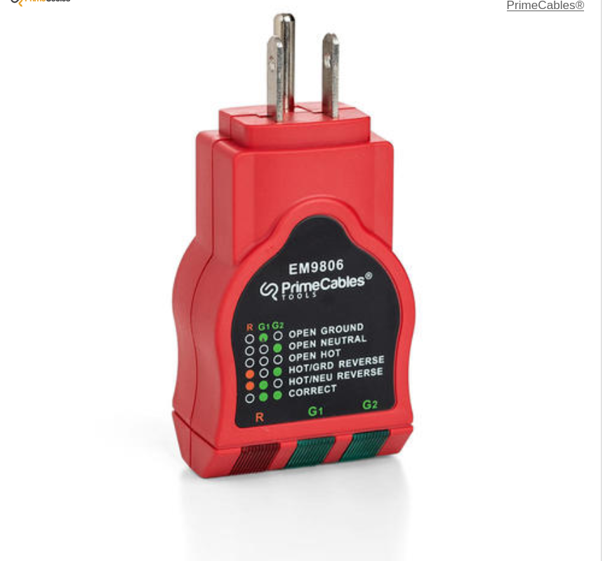
    The method of testing mentioned above will only be reliable if the wall receptacle has been wired correctly.

    Handy gizmo for new house purchase or those who rent.

    Last edited by alloy2; 10-17-2021 at 12:10 PM.

  20. #18
    SMF Badges of Honor


    Member since
    Apr 2015
    Posts
    2,168
    Thanks
    632
    Thanked 2,503 Times in 1,138 Posts
    These non contact voltage testers are inexpensive to own.

    This tester is capable of detecting live wire through the insulation so there's no need to bare a wire or pierce through the insulation. it will also let you know if your appliances are hot on the shell.


  21. #19
    cyberdan started this thread.
    cyberdan's Avatar
    SMF Badges of Honor


    Member since
    Feb 2013
    Location
    Del Norte County, CA
    Posts
    170
    Thanks
    8
    Thanked 111 Times in 47 Posts
    Quote Originally Posted by alloy2 View Post
    Wire color codes on offshore are confusing, for North America black is hot, white neutral with green to ground.

    Once you have the power connected with the motor running keep the ground wire disconnected then with your multi meter place one probe onto the motor shell with the other to the green ground.

    If polarization is incorrect your meter will show the motor shell is hot.
    I will be buying a multi meter today at Harbor Freight. I found one on feeBay and started to order then remembered there is a new Harbor Freight in town. It is a dollar cheaper and I do not have to wait one week.

    Harbor Freight also has both tools you recommended for $4.99 each. But I think the multimeter can be used many different ways.

    I am pretty sure my greenhouse/workshop is wired correctly even though I did all the wiring my self. (two on/off switches and 4 plug outlet all connected to a heavy duty extension cord I plug into an outside box on my home) Never had any problems. But I will also take inside and test in my office.

  22. #20
    SMF Badges of Honor


    Member since
    Apr 2015
    Posts
    2,168
    Thanks
    632
    Thanked 2,503 Times in 1,138 Posts
    Quote Originally Posted by cyberdan View Post
    I will be buying a multi meter today at Harbor Freight. I found one on feeBay and started to order then remembered there is a new Harbor Freight in town. It is a dollar cheaper and I do not have to wait one week.

    Harbor Freight also has both tools you recommended for $4.99 each. But I think the multimeter can be used many different ways.

    I am pretty sure my greenhouse/workshop is wired correctly even though I did all the wiring my self. (two on/off switches and 4 plug outlet all connected to a heavy duty extension cord I plug into an outside box on my home) Never had any problems. But I will also take inside and test in my office.

    This is my personal meter, I'm not going to give a course on how I use it but will give a few examples.

    Say I had a refrigerator that the compressor will not start, I can separate the incoming power cord or use the line splitter shown below the meter, Now that the meter is clamped onto the power cord.

    Once the fridge is turned trace the incoming power, to the thermostat, check thermostat fro continuity, test for power to compressor start relay, test compressor for start up amp draw.

    My meter tests both AC and DC current, if the meter was clamped onto the trucks battery positive side then when you engage the starter the amperage showing on the meter will indicate if the starter is on good or bad health.

    For instance worn armature bushings will cause the armature to rub against the field core causing excessive amps to be drawn.


  23. Similar threads on the Scrap Metal Forum

    1. Building semi-automatic small gauge wire stripper
      By KillYrTV in forum Made From Scrap
      Replies: 15
      Last Post: 02-03-2016, 04:05 PM
    2. Metal shielded building wire
      By drozenski in forum Scrap Metal Questions and Answers
      Replies: 3
      Last Post: 10-15-2011, 01:00 PM

Page 1 of 3 123 LastLast

Thread Information

Users Browsing this Thread

There are currently 1 users browsing this thread. (0 members and 1 guests)

 
Browse the Most Recent Threads
On SMF In THIS CATEGORY.


OR

Bookmarks

Posting Permissions

  • You may not post new threads
  • You may not post replies
  • You may not post attachments
  • You may not edit your posts
  •  

The Scrap Metal Forum

    The Scrap Metal Forum is the #1 scrap metal recycling community in the world. Here we talk about the scrap metal business, making money, where we connect with other scrappers, scrap yards and more.

SMF on Facebook and Twitter

Twitter Facebook